
Deformation Monitoring Background
Monitoring Deformation
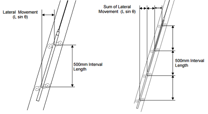
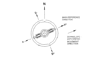
Top: Inclinometer measurement principle;
Bottom: Inclinometer casing with grooves
Inclinometers measure tilt, which is used in several calculations to quantify displacement and deflections of slopes, embankments and structures. Integrated MEMS (Micro-Electro-Mechanical-Systems) technology allows for sensing of both dynamic acceleration (i.e. shock or vibration) and static acceleration (i.e. inclination or rotation).
Inclinometers may be portable or in-place. In-place inclinometers consist of a series of sensors connected by extension rods, which are on a single bus to simplify cabling. Portable versions incorporate a wheeled probe with a cable on a reel. The probe is lowered into the casing and a portable readout logs the measurements. Special casings with four orthogonal grooves are used to lower inclinometers through the casing.
Extensometers are used to measure and locate settlement, heave displacement and deformation in soil and rock. A wide range including borehole rod, magnetic, and tape type extensometers are available for monitoring excavations, foundations, dams, embankments, tunnels, shafts and sheet piles.
A borehole rod type extensometer consists of a reference head and one or more in-hole anchors, each placed at known depth and connected to the reference head by either a rigid or flexible rod running inside a sleeve, which keeps the rod de-bonded from the grout.
A magnetic type works by lowering a Reed Switch Probe into an access casing which has a series of magnets fixed at known locations. Various magnet types and casing options are available to accommodate a range of different settlement conditions.
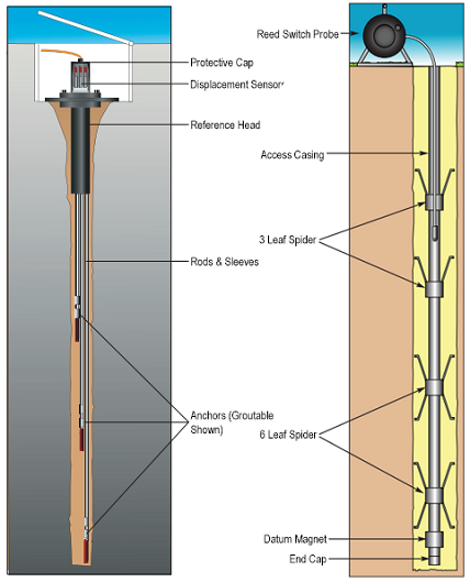 Left: Borehole rod extensometer;
Right: Magnetic extensometer
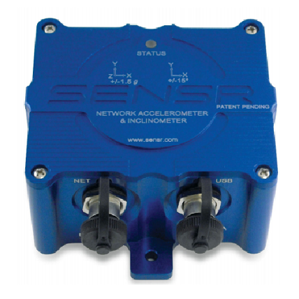
Tilt Sensor Example
Tilt sensors detect and monitor differential movement and rotation in structures. They typically incorporate MEMS accelerometers and are mounted onto structures (differently from inclinometers mounted in casings) to detect movement caused by settlement and heave. Several different types are available to suit various applications, including portable, in-place and submersible tilt meters or tilt beams that can be bussed together to provide settlement profiles along a structure.
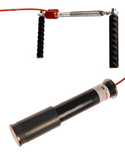
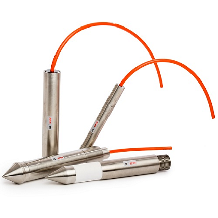
Strain gauges are firmly fixed to the object being measured and have a certain electrical resistance. As the object deforms, the electrical resistance changes, and the overall strain can be determined from this. Many strain gauges used in geotechnical applications incorporate a vibrating wire output for interface with portable readouts and autonomous data collection systems. Deformations cause movement in the gauge that changes the frequency of the wire.
Embedment type gauges are designed for direct embedment in concrete.
Surface mount type gauges are attached to steel structures by arc welding or to concrete structures by bonding or grouting into concrete structures.
Rebar strain gauges are welded into concrete rebar systems as load bearing members of the rebar structure. Thus, they measure strain on the reinforcement cage itself.
Sister bar gauges are similar to rebar gauges but are fixed alongside rebar members so that they measure the strain of the concrete rather than the rebar structure.
Spot weld type gauges are primarily used to measure strain on the surface of steel structural members.
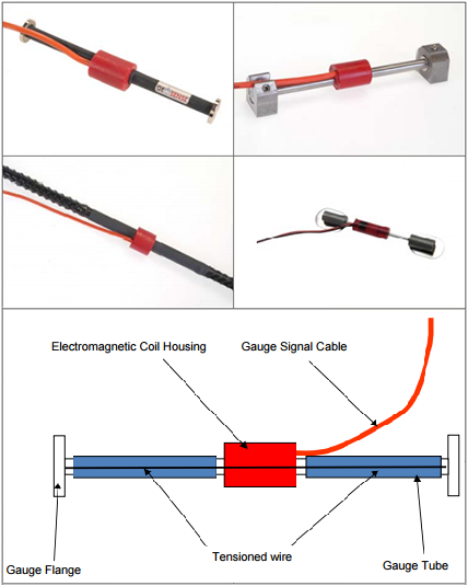
Top: Embedment type (left); Surface mount type;
Middle: Rebar/sister bar type (left); Spot weld type;
Bottom: Strain gauge components
Top: Crack meter;
Bottom: Joint meter
Joint and crack meters are designed to measure displacements across joints and cracks typically in buildings, bridges, dams, pipelines and rock formations. They are available for measuring movement in one (1D) or three axes (3D).
Joint meters are ideal for monitoring movement of joints within mass-concrete structures such as abutments, slabs, foundations, retaining walls, tunnel or shaft linings, and arch, gravity and buttress dams.
Crack meters operate similarly to joint meters but are used for measuring cracks on the surface of an object such as a crack in a concrete wall or a rock structure.
Piezometers measure the pressure exerted on soil or rock from fluids located within the voids between the individual particles comprising the soil or rock. They can be useful in monitoring the underlying conditions that can lead to deformations in soil or structures. Click here for more information on pore pressure monitoring systems and applications.
Piezometers
SAAF demonstration video
SAAF (ShapeAccelArrayField) is a unique system for deformation measurement. It consists of a rope-like array of sensors and microprocessors that fits into a small (27 mm; 1.05” ID) casing. Any deformation that moves the casing it accurately measured as a change in shape of the SAAF. The SAAF can also be used to detect vibrations.
The arrays usually arrive on a reel with lengths up to 100m. This allows simple installation into the casing. The individual segments are either 30 or 50 cm in length, contain three MEMS accelerometers each, and are connected by flexible joints. Similar to inclinometers, it provides measurements based on tilt but sends data in a digital format. A piezometer can also be integrated into the system.
Some of the advantages of SAAF include that it is simple to install from the reel, measures at hundreds of locations in either a horizontal or vertical arrangement, withstands huge deformations without getting trapped in the casing, and can be reused at multiple locations.
Data Management
Many of the sensors mentioned above are available in either portable or fixed options, and the fixed options can often be read intermittently by a handheld unit or by connection to an autonomous data logging and telemetry system. Automated data collection systems allow the system to continuously gather data, transmit in real-time, and provide alarm notifications immediately when a threshold condition is exceeded. This can be of great value for notifying construction teams or maintenance workers of a hazardous condition before it poses a serious safety threat.
Data collection in automated systems is performed using data loggers such as those from Campbell Scientific or the Cautus Logger from Cautus Geo. These are multi-input units that allow connection of many devices simultaneously, so complete monitoring networks are easily achievable. Data telemetry is commonly achieved through GSM/GPRS communications, though other options including spread spectrum radio, satellite and Ethernet also are available.
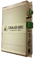
Cautus Logger
Another important part of deformation monitoring is to present information in a user friendly way. Web data management systems such as Cautus Geo’s Cautus Web simplify this task. Cautus Web was developed based on expertise gained through being a service provider for large and complex monitoring projects for many years. It is a complete data management and early warning system for geo-monitoring projects, providing an ideal solution for real-time monitoring of unstable areas and constructions. The datacenter is module based and provides everything from an overview map to automated alarm notifications to detailed data analysis.
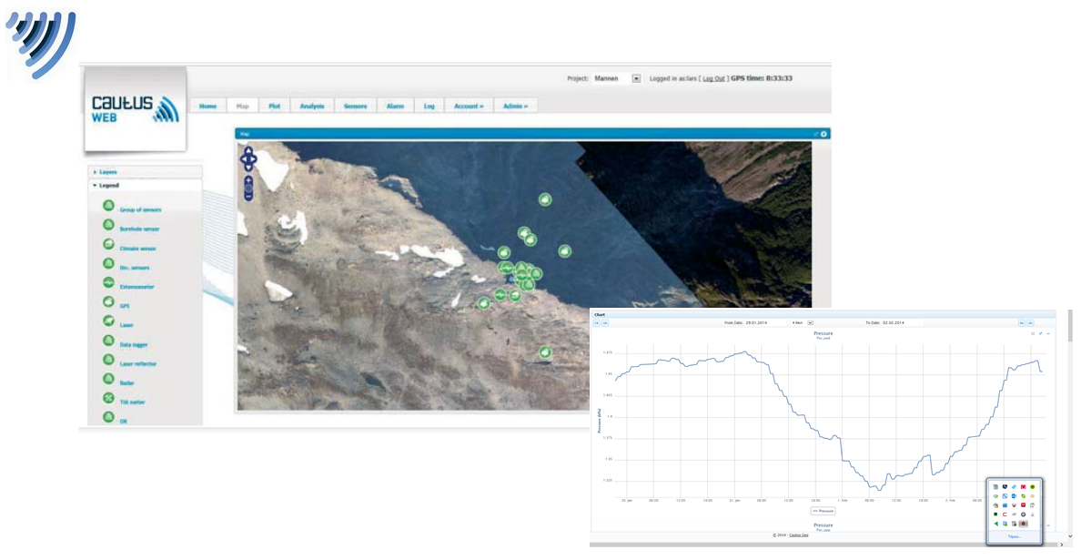
Data Management in Cautus Web
Getting Started
MeasureIt personnel have an extensive background in geotechnical monitoring applications. We can help you source equipment from the industry’s leading manufacturers and provide guidance to help you set up a successful monitoring network.
>> Contact us today to discuss your application!
>> Browse products:
- Inclinometers
- Extensometers
- Tilt Sensors
- Strain Gauges
- Joint & Crack Meters
- Piezometers
- SAAF
- Data Loggers
- Cautus Web